
Forklift lithium battery startup: how BMS permission, precharge and contactors work
A forklift can display a state-of-charge reading and communicate with its BMS while travel and lifting remain unavailable. Understanding startup means separating the energy stored in the cells from discharge permission, the actual state of the main contacts and the vehicle's operating permissions.
This explanation covers contactor-controlled systems with a precharge function. Precharge can be on the battery side or the vehicle side. The functions described here do not specify a startup sequence for an individual battery or truck.
Stored energy, discharge permission and the main power path
Energy inside the cells
The cells store energy and connect in the arrangement required by the battery design. Opening the external output circuit can leave the cells energized inside the pack. An absence of external output is therefore no indication that the battery is safe to open or work on.
BMS discharge permission
The BMS uses measurements such as cell voltage, temperature and current, together with its configured limits, to determine whether discharge is permitted. That permission is a control decision. The Orion BMS 2 wiring manual, for example, describes a discharge-enable signal to control other equipment. The main power circuit carries the current supplied to the vehicle.
For more on monitoring and protection, see the forklift battery BMS technology guide.
Contactors and the main circuit fuse
A contactor is an electrically controlled switch. Its coil belongs to the control circuit, while its main contacts carry power current. Sending a close command does not establish that the contacts have closed; the availability and interpretation of contact-state feedback depend on the design.
The main circuit fuse interrupts current when its operating conditions are met. It provides fault-current protection, not the routine switching or discharge-permission functions.
Precharge supplies controller capacitors, not battery cells
Many motor controllers have capacitors at their power inputs. Connecting them directly to a battery through a low-impedance path can produce a large initial charging current when their voltage differs substantially from the battery voltage. Sensata's application note on precharge circuits and capacitors explains how this inrush can damage contactors.
Precharge limits that current while voltage builds across the input capacitors, reducing the voltage difference before the main operating path connects. It does not replenish the battery's state of charge.
In a resistor-based arrangement, the precharge branch limits current during this process and the main path carries normal operating current. The circuit design determines which contacts switch, how the controls assess precharge completion and what happens to the precharge branch afterward.
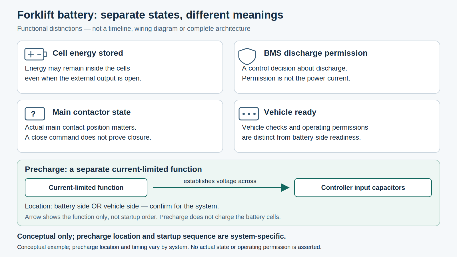
Is precharge the battery's responsibility or the vehicle's?
Either arrangement is possible. A battery can contain precharge components, or the vehicle can provide the function. The absence of a precharge resistor inside the battery enclosure does not establish that the complete system lacks precharge.
When purchasing or replacing a battery, ask which side provides the hardware and which control unit starts precharge and checks its status. The answer also needs to identify the capacitive loads involved and how precharge status coordinates with main contactor control.
Battery and vehicle documentation should agree on the enable signals, permissions and status information exchanged between them. Matching rated voltage, capacity and connector shape alone cannot establish that the control systems are compatible.
How startup functions work together
Control power and wake-up
The BMS and other control components need their specified power supplies and wake-up conditions. Key signals and DC-DC supplies can be involved, but the source of control power and the wake-up method depend on the installation.
Discharge permission, precharge and switching
The BMS discharge decision, capacitor precharge and contactor switching must coordinate with the vehicle controls. A description of the actual startup process needs to identify the switching arrangement, the conditions for each transition and which control unit is responsible. A functional diagram alone cannot establish that timing.
Vehicle readiness
Even with battery output available, the vehicle can still require its own checks and operating permissions. During service discussions, ask what a reported "ready" state means: BMS permission to discharge, an established main power path, or permission for travel and hydraulic operation. Those states answer different questions.
What documentation should purchasing and service teams request?
Ask for a functional diagram and startup-state descriptions that match the battery, controller and truck configuration. The documents should assign responsibility between battery and vehicle controls and distinguish precharge status, contactor commands, actual contact state and vehicle readiness.
A displayed state of charge, BMS communication or a contactor close command is insufficient on its own to diagnose why a truck will not operate. Service personnel need the system-specific documentation and approved procedures. Do not bypass discharge permissions, precharge or protection functions to test startup.
EPL154Z and KBP15 Battery Check: Dimensions and Plug Details